[ Comprehensive Guide ]
HOW TO DEVELOP A
PHYSICAL PRODUCT:
FROM IDEA TO MARKET
A complete guide to the product development process, from concept brief to factory floor. By the engineering team at ONMOTIO.
[ Quick Answer ]
What is the process of developing a physical product?
The process of developing a physical product involves six key stages: defining the product brief, exploring divergent design concepts, selecting and refining the final concept, developing detailed mechanical engineering specifications, building and testing physical prototypes, and preparing the finalized design for mass manufacturing. Each stage is designed to systematically reduce technical and commercial risk while transforming an abstract idea into a reliable, production-ready system.
Introduction
Developing a physical product is a complex, multi-disciplinary process that combines industrial design, mechanical engineering, prototyping, and manufacturing preparation. Whether you are a funded startup founder, an established entrepreneur, or an enterprise team launching a new hardware device, understanding this end-to-end process is critical to avoid costly tooling mistakes, supply chain delays, and market failure.
Unlike software or digital products, physical hardware must navigate uncompromising real-world constraints: material properties, manufacturing tolerances, supply chain logistics, and physical performance under stress. This makes physical product development more demanding, requiring a highly structured, risk-mitigating approach from day one.
This comprehensive guide breaks down the full lifecycle of developing a physical product, taking you from the initial concept brief to a fully manufacturable, market-ready device.
[ The Process ]
The 6 Key Stages of Product Development
Every successful hardware product follows a structured path from abstract idea to factory-ready system.
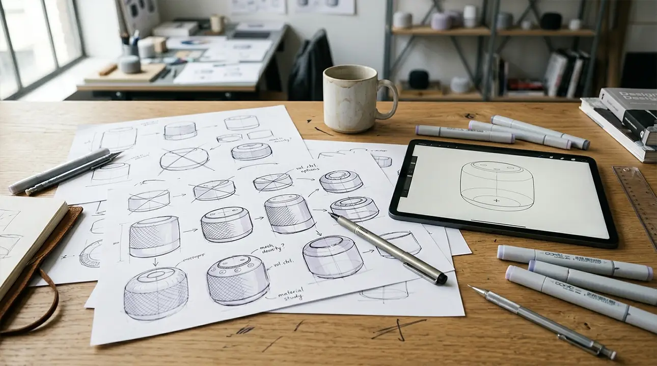
First stage
Product Definition & Brief
Transform a loose idea into an uncompromising, structured framework that dictates all subsequent engineering and design decisions.
The graveyard of hardware startups is littered with products that began as a brilliant idea but lacked a rigorous definition. A physical product cannot pivot on a dime the way software can. In software, changing a core feature mid-development requires rewriting code. In hardware, changing a core feature mid-development requires throwing away physical prototypes, scrapping expensive steel molds, renegotiating supplier contracts, and delaying your launch by months.
Because the cost of iteration rises exponentially as you move from concept to factory floor, the first stage of development must be ruthlessly precise. The goal of this stage is not to design a product; it is to define the absolute boundaries within which the product will be designed.
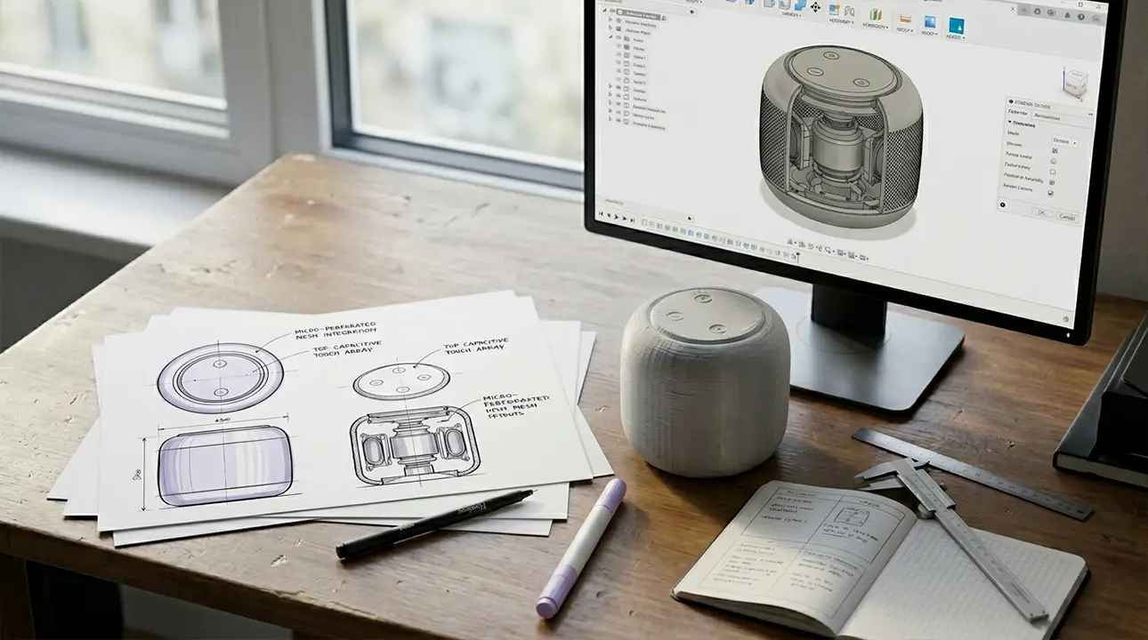
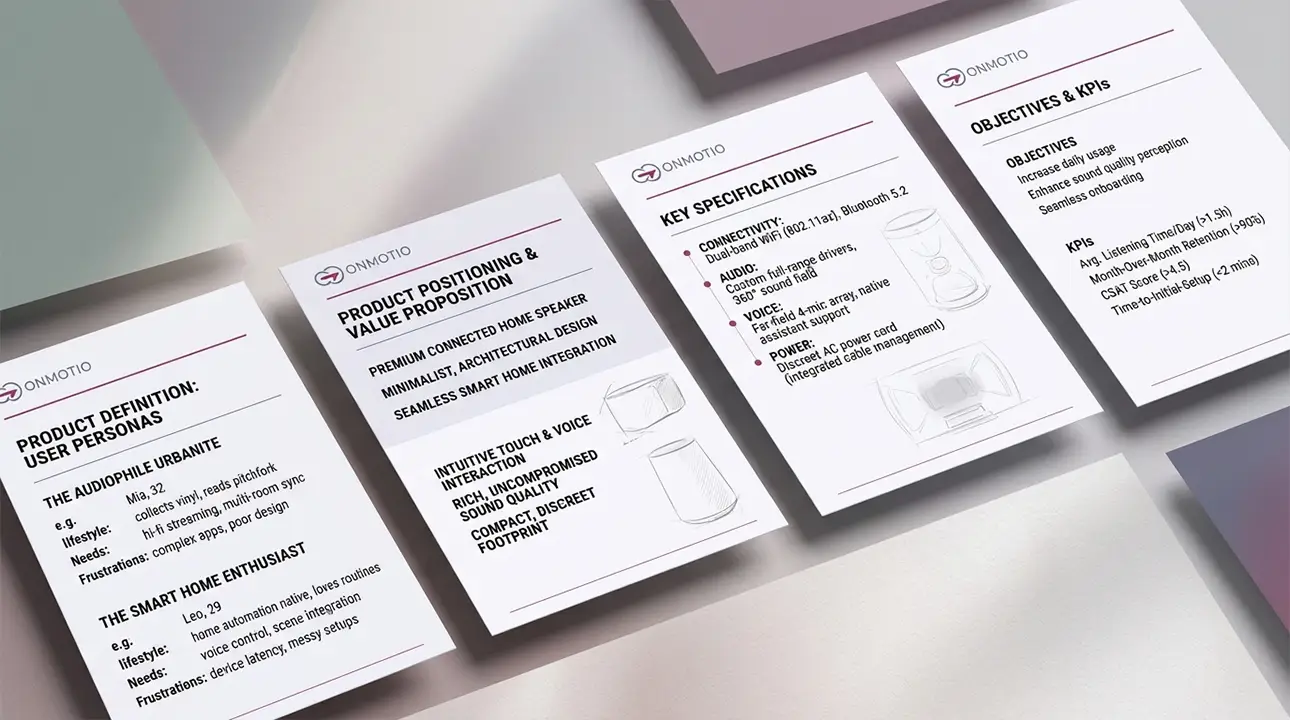
The Product Requirements Document (PRD)
The cornerstone of this phase is the Product Requirements Document (PRD). This is not a marketing brief; it is a technical contract between the founders, the industrial designers, and the mechanical engineers. A professional PRD translates vague aspirations ("it needs to be lightweight and durable") into measurable engineering metrics ("it must weigh less than 450 grams and survive a 1.5-meter drop onto concrete").
The PRD serves as the single source of truth for the entire development lifecycle. It establishes the absolute boundaries within which the engineering team must operate. If a feature is not in the PRD, it does not exist. If a constraint is not in the PRD, it cannot be enforced later without severe financial penalties.
Establishing the Commercial Envelope
Engineering in a vacuum is dangerous. A product can be technically flawless but commercially unviable if it costs too much to manufacture. During the definition stage, the team must establish the Target Cost of Goods Sold (COGS).
If the retail price of your device is